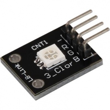
SMD RGB LED module consists of a full-color LED made by R, G, B three pin PWM voltage input can be adjusted. Primary colors (red / blue / green) strength in order to achieve full color mixing effect. Control of the module with the Arduino can be achieved Cool lighting effects.
A LED-module which provides a red, blue and green LED. These are connected with a common cathode. A resistor is necessary for different voltages.
Vf [Red]= 1,8V
Vf [Green,Blue]= 2,8V
If= 20mA
Pre-resistor:
Rf (3,3V) [Green]= 100Ω
Rf (3,3V) [Red]= 180Ω
Rf (3,3V) [Blue]= 100Ω
[for example using of ARM CPU-Core based microcontroller like Raspberry-Pi]
Rf (5V) [Green] = 100Ω
Rf (5V) [Red] = 180Ω
Rf (5V) [Blue] = 100Ω
[for example using of Atmel Atmega based microcontroller like Arduino]
Arduino Connections with KY-009 RGB LED Module

Since you can’t connect the led’s directly to the Arduino you will need resistors!!
Arduino pin 9 –> 110 Ohm resistor –> Pin ‘G’ of KY-009 module
Arduino pin 10 –> 110 Ohm resistor –> Pin ‘B’ of KY-009 module
Arduino pin 11 –> 180 Ohm resistor –> Pin ‘R’ of KY-009 module
Arduino GND –> pin ‘-‘ of KY-009 module
Arduino Code for KY-009 Module Interface
Note: Always use PWM Pins for RGB Led Module
This module provides a few LEDs – with the overlay of the different brightness levels, you can create different colors. This will be shown in the following code example. At the Raspberry Pi, only one Hardware-PWM channel is carried out unrestricted to the GPIO pins, that’s why we have used Software-PWM on this example.
// RGB LED KY-009 Module

int Led_Green = 9;
int Led_Blue = 10;
int Led_Red = 11;

int val;

void setup () {
  //Output pin initialization for the LEDs
  pinMode (Led_Red, OUTPUT);
  pinMode (Led_Green, OUTPUT);
  pinMode (Led_Blue, OUTPUT);
}
void loop () {
   // In this for-loop, the 3 LEDs will get different PWM-values
   // Via mixing the brightness of the different LEDs, you will get different colors.
   for (val = 255; val> 0; val--)
      {
       analogWrite (Led_Blue, val);
       analogWrite (Led_Green, 255-val);
       analogWrite (Led_Red, 128-val);
       delay (1);
   }
   // You will go backwards through the color range in this second for loop.
   for (val = 0; val <255; val++)
      {
      analogWrite (Led_Blue, val);
      analogWrite (Led_Green, 255-val);
      analogWrite (Led_Red, 128-val);
      delay (1);
   }
}
You can regulate the brightness of the LEDs via pulse-width modulation. The LEDs will be switched ON and OFF for specific time periods, in which the relation between ON and OFF leads to a relative brightness, because of the Inertia of the human eyesight, the human eye interprets the ON/OFF as a brightness change.


Responses