Network synchronized digital time displays are designed to provide accurate time referenced, NTP server, or time code source. It offers simplicity and no need of setting time. NodeMCU based this simple clock provides accurate time display and uses only NodeMCU and Matrix Display modules. Lets Make it.
Step 1: Components Required
- NodeMCU Qty 1.
- MAXIM Matrix Display Modules Qty. 2
- Wires
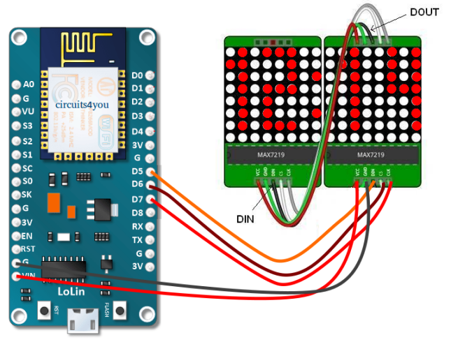
Step 2: Circuit Connections for NTP Clock
Make connections as shown in below circuit diagram.
Step 3: Programming NTP NodeMCU Clock
Program is divided in two parts first part manages network related functions and included files to control display. Configure your Network settings SSID and Password in program and UTC Time settings. LEDMatrix display library is modified to work with ESP8266.
Main Program.ino
/*
    ESP8266 NodeMCU NTP (Network Time Protocol) Example
    Hardware: NodeMCU
    Date: 2018
    https://circuits4you.com
    Referances
    https://circuits4you.com/2016/05/19/max7219-segment-display-arduino/
    https://circuits4you.com/2016/10/07/moving-message-display-arduino/
    https://circuits4you.com/2017/12/31/nodemcu-pinout/
    https://circuits4you.com/2018/01/02/esp8266-timer-ticker-example/
    https://circuits4you.com/2018/01/02/esp8266-nodemcu-ntp-time-clock/
*/
#include
#include
#include "LEDMatrix.h"
#include   //Ticker Library

Ticker blinker;
//========================= Matrix Display ===========================
//Blinked state
int state=0;
//Connections for matrix display
const int data  = 14;     // DIN or MOSI
const int load  = 12;     // CS
const int clock = 13;     // SCK
LedControl disp=LedControl(data,clock,load,2);  //Set connections and Number of displays
const unsigned char CH[][4] = {
  B1111111, B1000001, B1111111, B0000000, // 0
  B0000010, B1111111, B0000000, B0000000, // 1
  B1111001, B1001001, B1001111, B0000000, // 2
  B1001001, B1001001, B1111111, B0000000, // 3
  B0001111, B0001000, B1111111, B0000000, // 4
  B1001111, B1001001, B1111001, B0000000, // 5
  B1111111, B1001001, B1111001, B0000000, // 6
  B0000111, B0000001, B1111111, B0000000, // 7
  B1111111, B1001001, B1111111, B0000000, // 8
  B1001111, B1001001, B1111111, B0000000  // 9
};
//============================ UDP and WiFi ============================
char ssid[] = "circuits4you.com";  //  your network SSID (name)
char pass[] = "********";       // your network password
//Your UTC Time Zone Differance  India +5:30
char HH = 5;
char MM = 30;
unsigned int localPort = 2390;      // local port to listen for UDP packets
/* Don't hardwire the IP address or we won't get the benefits of the pool.
 *  Lookup the IP address for the host name instead */
//IPAddress timeServer(129, 6, 15, 28); // time.nist.gov NTP server
IPAddress timeServerIP; // time.nist.gov NTP server address
const char* ntpServerName = "time.nist.gov";
const int NTP_PACKET_SIZE = 48; // NTP time stamp is in the first 48 bytes of the message
byte packetBuffer[ NTP_PACKET_SIZE]; //buffer to hold incoming and outgoing packets
// A UDP instance to let us send and receive packets over UDP
WiFiUDP udp;
//=======================================================================
//                     BLINKING CENTER DOTS
//=======================================================================
void changeState()
{
 if(state==1)
 {
   disp.setRow(1,7,0x00);
   state=0;
 }
 else
 {
    disp.setRow(1,7,0x24);
    state=1;
 }
}
//=======================================================================
//                     DISPLAY
//=======================================================================
void Display(int pos, int n)
{
  int i;
  if(pos == 0)
  {
    if(n==1)
    {disp.setRow(1,1,0x7F);disp.setRow(1,0,0x02);}
    else
    {disp.setRow(1,1,0x00);disp.setRow(1,0,0x00);}
  }

  if(pos == 1)
  {
    for(i=0;i<4;i++)
    {
      disp.setRow(1,i+3,CH[n][i]);
    }
  }

  if(pos == 2)
  {
    for(i=0;i<4;i++)
    {
      disp.setRow(0,i+1,CH[n][i]);
    }
  }
  if(pos == 3)
  {
    for(i=0;i<4;i++)
    {
      disp.setRow(0,i+5,CH[n][i]);
    }
  }
}
//=======================================================================
//                     SETUP
//=======================================================================
void setup()
{
  Serial.begin(115200);
  Serial.println();
  Serial.println();
  //----------------Matrix Display ---------------
  disp.shutdown(0,false);
  disp.shutdown(1,false);

  /* Set the brightness to a medium values */
  disp.setIntensity(0,3);
  disp.setIntensity(1,3);

  /* and clear the display */
  disp.clearDisplay(0);
  disp.clearDisplay(1);
  Display(0,1);
  Display(1,2);
  Display(2,3);   //Digit and Number to be displayed
  Display(3,4);
  delay(2000);
  Display(0,5);
  Display(1,1);
  Display(2,7);   //Digit and Number to be displayed
  Display(3,9);


  //Initialize Ticker every 0.5s
    blinker.attach(0.5, changeState);
  //----------------------------------------------
  // We start by connecting to a WiFi network
  Serial.print("Connecting to ");
  Serial.println(ssid);
  WiFi.mode(WIFI_STA);
  WiFi.begin(ssid, pass);

  while (WiFi.status() != WL_CONNECTED) {
    delay(500);
    Serial.print(".");
  }
  Serial.println("");

  Serial.println("WiFi connected");
  Serial.println("IP address: ");
  Serial.println(WiFi.localIP());
  Serial.println("Starting UDP");
  udp.begin(localPort);
  Serial.print("Local port: ");
  Serial.println(udp.localPort());
}
//=======================================================================
//  send an NTP request to the time server at the given address
//=======================================================================
unsigned long sendNTPpacket(IPAddress& address)
{
  Serial.println("sending NTP packet...");
  // set all bytes in the buffer to 0
  memset(packetBuffer, 0, NTP_PACKET_SIZE);

  // Initialize values needed to form NTP request
  // (see URL above for details on the packets)
  packetBuffer[0] = 0b11100011;   // LI, Version, Mode
  packetBuffer[1] = 0;     // Stratum, or type of clock
  packetBuffer[2] = 6;     // Polling Interval
  packetBuffer[3] = 0xEC;  // Peer Clock Precision
  // 8 bytes of zero for Root Delay & Root Dispersion
  packetBuffer[12]  = 49;
  packetBuffer[13]  = 0x4E;
  packetBuffer[14]  = 49;
  packetBuffer[15]  = 52;
  // all NTP fields have been given values, now
  // you can send a packet requesting a timestamp:

  udp.beginPacket(address, 123); //NTP requests are to port 123
  udp.write(packetBuffer, NTP_PACKET_SIZE);
  udp.endPacket();
}
//=======================================================================
//                        LOOP
//=======================================================================
void loop()
{
  char hours, minutes, seconds;
  //get a random server from the pool
  WiFi.hostByName(ntpServerName, timeServerIP);
  sendNTPpacket(timeServerIP); // send an NTP packet to a time server
  // wait to see if a reply is available
  delay(1000);

  int cb = udp.parsePacket();
  if (!cb) {
    Serial.println("no packet yet");
  }
  else {
    Serial.print("packet received, length=");
    Serial.println(cb);
    // We've received a packet, read the data from it
    udp.read(packetBuffer, NTP_PACKET_SIZE); // read the packet into the buffer
    //the timestamp starts at byte 40 of the received packet and is four bytes,
    // or two words, long. First, esxtract the two words:
    unsigned long highWord = word(packetBuffer[40], packetBuffer[41]);
    unsigned long lowWord = word(packetBuffer[42], packetBuffer[43]);
    // combine the four bytes (two words) into a long integer
    // this is NTP time (seconds since Jan 1 1900):
    unsigned long secsSince1900 = highWord << 16 | lowWord;
    Serial.print("Seconds since Jan 1 1900 = " );
    Serial.println(secsSince1900);
    // now convert NTP time into everyday time:
    Serial.print("Unix time = ");
    // Unix time starts on Jan 1 1970. In seconds, that's 2208988800:
    const unsigned long seventyYears = 2208988800UL;
    // subtract seventy years:
    unsigned long epoch = secsSince1900 - seventyYears;
    // print Unix time:
    Serial.println(epoch);
    // print the hour, minute and second:
    minutes = ((epoch % 3600) / 60);
    minutes = minutes + MM; //Add UTC Time Zone

    hours = (epoch  % 86400L) / 3600;
    if(minutes > 59)
    {
      hours = hours + HH + 1; //Add UTC Time Zone
      minutes = minutes - 60;
    }
    else
    {
      hours = hours + HH;
    }
    if(hours>12)    //Convert to 12 hours format
    { hours = hours - 12; }

    Serial.print("The UTC time is ");       // UTC is the time at Greenwich Meridian (GMT)
    Display(0, hours/10);
    Display(1, (hours-((hours/10)*10)));

    Serial.print(hours,DEC); // print the hour (86400 equals secs per day)
    Serial.print(':');

    if ( minutes < 10 ) {
      // In the first 10 minutes of each hour, we'll want a leading '0'
      Serial.print('0');
      Display(2, 0);
    }

    Display(2, minutes/10);
    Display(3, (minutes-((minutes/10)*10)));

    Serial.print(minutes,DEC); // print the minute (3600 equals secs per minute)
    Serial.print(':');

    seconds = (epoch % 60);
    if ( seconds < 10 ) {
      // In the first 10 seconds of each minute, we'll want a leading '0'
      Serial.print('0');
    }
    Serial.println(seconds,DEC); // print the second
  }
  // wait ten seconds before asking for the time again
  delay(10000);
}
//=======================================================================
LEDMatrix.CPP
#include "LEDMatrix.h"
//the opcodes for the MAX7221 and MAX7219
#define OP_NOOP   0
#define OP_DIGIT0 1
#define OP_DIGIT1 2
#define OP_DIGIT2 3
#define OP_DIGIT3 4
#define OP_DIGIT4 5
#define OP_DIGIT5 6
#define OP_DIGIT6 7
#define OP_DIGIT7 8
#define OP_DECODEMODE  9
#define OP_INTENSITY   10
#define OP_SCANLIMIT   11
#define OP_SHUTDOWN    12
#define OP_DISPLAYTEST 15
LedControl::LedControl(int dataPin, int clkPin, int csPin, int numDevices) {
    SPI_MOSI=dataPin;
    SPI_CLK=clkPin;
    SPI_CS=csPin;
    if(numDevices<=0 || numDevices>8 )
        numDevices=8;
    maxDevices=numDevices;
    pinMode(SPI_MOSI,OUTPUT);
    pinMode(SPI_CLK,OUTPUT);
    pinMode(SPI_CS,OUTPUT);
    digitalWrite(SPI_CS,HIGH);
    SPI_MOSI=dataPin;
    for(int i=0;i<64;i++)
        status[i]=0x00;
    for(int i=0;i<maxdevices;i++) {
        spiTransfer(i,OP_DISPLAYTEST,0);
        //scanlimit is set to max on startup
        setScanLimit(i,7);
        //decode is done in source
        spiTransfer(i,OP_DECODEMODE,0);
        clearDisplay(i);
        //we go into shutdown-mode on startup
        shutdown(i,true);
    }
}
int LedControl::getDeviceCount() {
    return maxDevices;
}
void LedControl::shutdown(int addr, bool b) {
    if(addr<0 || addr>=maxDevices)
        return;
    if(b)
        spiTransfer(addr, OP_SHUTDOWN,0);
    else
        spiTransfer(addr, OP_SHUTDOWN,1);
}
void LedControl::setScanLimit(int addr, int limit) {
    if(addr<0 || addr>=maxDevices)
        return;
    if(limit>=0 && limit<8)
        spiTransfer(addr, OP_SCANLIMIT,limit);
}
void LedControl::setIntensity(int addr, int intensity) {
    if(addr<0 || addr>=maxDevices)
        return;
    if(intensity>=0 && intensity<16)
        spiTransfer(addr, OP_INTENSITY,intensity);
}
void LedControl::clearDisplay(int addr) {
    int offset;
    if(addr<0 || addr>=maxDevices)
        return;
    offset=addr*8;
    for(int i=0;i<8;i++) {
        status[offset+i]=0;
        spiTransfer(addr, i+1,status[offset+i]);
    }
}
void LedControl::setLed(int addr, int row, int column, boolean state) {
    int offset;
    byte val=0x00;
    if(addr<0 || addr>=maxDevices)
        return;
    if(row<0 || row>7 || column<0 || column>7)
        return;
    offset=addr*8;
    val=B10000000 >> column;
    if(state)
        status[offset+row]=status[offset+row]|val;
    else {
        val=~val;
        status[offset+row]=status[offset+row]&val;
    }
    spiTransfer(addr, row+1,status[offset+row]);
}
void LedControl::setRow(int addr, int row, byte value) {
    int offset;
    if(addr<0 || addr>=maxDevices)
        return;
    if(row<0 || row>7)
        return;
    offset=addr*8;
    status[offset+row]=value;
    spiTransfer(addr, row+1,status[offset+row]);
}
void LedControl::setColumn(int addr, int col, byte value) {
    byte val;
    if(addr<0 || addr>=maxDevices)
        return;
    if(col<0 || col>7)
        return;
    for(int row=0;row<8;row++) {
        val=value >> (7-row);
        val=val & 0x01;
        setLed(addr,row,col,val);
    }
}
void LedControl::spiTransfer(int addr, volatile byte opcode, volatile byte data) {
    //Create an array with the data to shift out
    int offset=addr*2;
    int maxbytes=maxDevices*2;
    for(int i=0;i<maxbytes;i++)
        spidata[i]=(byte)0;
    //put our device data into the array
    spidata[offset+1]=opcode;
    spidata[offset]=data;
    //enable the line
    digitalWrite(SPI_CS,LOW);
    //Now shift out the data
    for(int i=maxbytes;i>0;i--)
        shiftOut(SPI_MOSI,SPI_CLK,MSBFIRST,spidata[i-1]);
    //latch the data onto the display
    digitalWrite(SPI_CS,HIGH);
}
</maxbytes;i++)
LEDMatrix.h
#ifndef LedControl_h
#define LedControl_h
#if (ARDUINO >= 100)
#include
#else
#include
#endif
class LedControl {
    private :
        /* The array for shifting the data to the devices */
        byte spidata[16];
        /* Send out a single command to the device */
        void spiTransfer(int addr, byte opcode, byte data);
        /* We keep track of the led-status for all 8 devices in this array */
        byte status[64];
        /* Data is shifted out of this pin*/
        int SPI_MOSI;
        /* The clock is signaled on this pin */
        int SPI_CLK;
        /* This one is driven LOW for chip selectzion */
        int SPI_CS;
        /* The maximum number of devices we use */
        int maxDevices;
    public:
        /*
         * Create a new controler
         * Params :
         * dataPin		pin on the Arduino where data gets shifted out
         * clockPin		pin for the clock
         * csPin		pin for selecting the device
         * numDevices	maximum number of devices that can be controled
         */
        LedControl(int dataPin, int clkPin, int csPin, int numDevices=1);
        /*
         * Gets the number of devices attached to this LedControl.
         * Returns :
         * int	the number of devices on this LedControl
         */
        int getDeviceCount();
        /*
         * Set the shutdown (power saving) mode for the device
         * Params :
         * addr	The address of the display to control
         * status	If true the device goes into power-down mode. Set to false
         *		for normal operation.
         */
        void shutdown(int addr, bool status);
        /*
         * Set the number of digits (or rows) to be displayed.
         * See datasheet for sideeffects of the scanlimit on the brightness
         * of the display.
         * Params :
         * addr	address of the display to control
         * limit	number of digits to be displayed (1..8)
         */
        void setScanLimit(int addr, int limit);
        /*
         * Set the brightness of the display.
         * Params:
         * addr		the address of the display to control
         * intensity	the brightness of the display. (0..15)
         */
        void setIntensity(int addr, int intensity);
        /*
         * Switch all Leds on the display off.
         * Params:
         * addr	address of the display to control
         */
        void clearDisplay(int addr);
        /*
         * Set the status of a single Led.
         * Params :
         * addr	address of the display
         * row	the row of the Led (0..7)
         * col	the column of the Led (0..7)
         * state	If true the led is switched on,
         *		if false it is switched off
         */
        void setLed(int addr, int row, int col, boolean state);
        /*
         * Set all 8 Led's in a row to a new state
         * Params:
         * addr	address of the display
         * row	row which is to be set (0..7)
         * value	each bit set to 1 will light up the
         *		corresponding Led.
         */
        void setRow(int addr, int row, byte value);
        /*
         * Set all 8 Led's in a column to a new state
         * Params:
         * addr	address of the display
         * col	column which is to be set (0..7)
         * value	each bit set to 1 will light up the
         *		corresponding Led.
         */
        void setColumn(int addr, int col, byte value);
};
#endif	//LEDMatrix.h
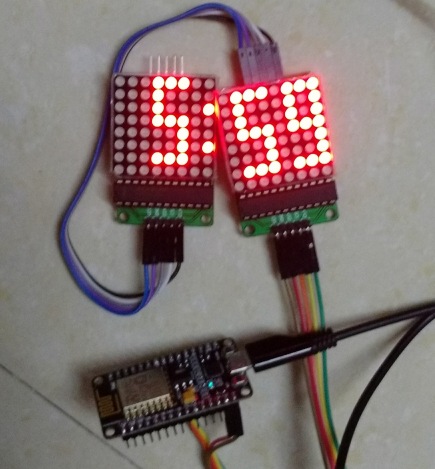
Step 4: Results
Open serial monitor to see if any errors are there. Your Clock is ready to display time. If you have forgotten SSID and Password it will not show time.
Step 5: References
- https://circuits4you.com/2016/05/19/max7219-segment-display-arduino/
- https://circuits4you.com/2016/10/07/moving-message-display-arduino/
- https://circuits4you.com/2017/12/31/nodemcu-pinout/
- https://circuits4you.com/2018/01/02/esp8266-timer-ticker-example/
- https://circuits4you.com/2018/01/02/esp8266-nodemcu-ntp-time-clock/


it looks like “>” and “<" symbols in code ware recognized as html tags and all include commands now have no parameters.