We live in an exciting time where more and more everyday items “things” are becoming smart! “Things” have sensors and can communicate to other “things” and can provide control to more “things”. The Internet of Things, IoT, is upon us in a huge way and people are rapidly inventing new gadgets that enhance our lives. The price of microcontrollers with the ability to talk over a network keeps dropping and developers can now tinker and build things inexpensively.
IoT based home automation project is done using low cost ESP8266 ESPino ESP-12 WiFi Module, It uses relays and few simple components, complete code is provided, for more details on software setup go through IoT getting started tutorial. You can control four electrical devices and also you can monitor temperature. ESP-12 is low cost module we are using here.

Components Required
1. ESP-12 WiFi Module
2. LM1117-3.3V
3. Sugar Cube Relay – Qty.4
4. Resistors 10K, 1K,4.7K
5. Capacitor 1000uF, 10uF, 104 (0.1uF)
6. PBT-2 Connectors Qty. 5
7. ULN2003
8. 12V Power Supply
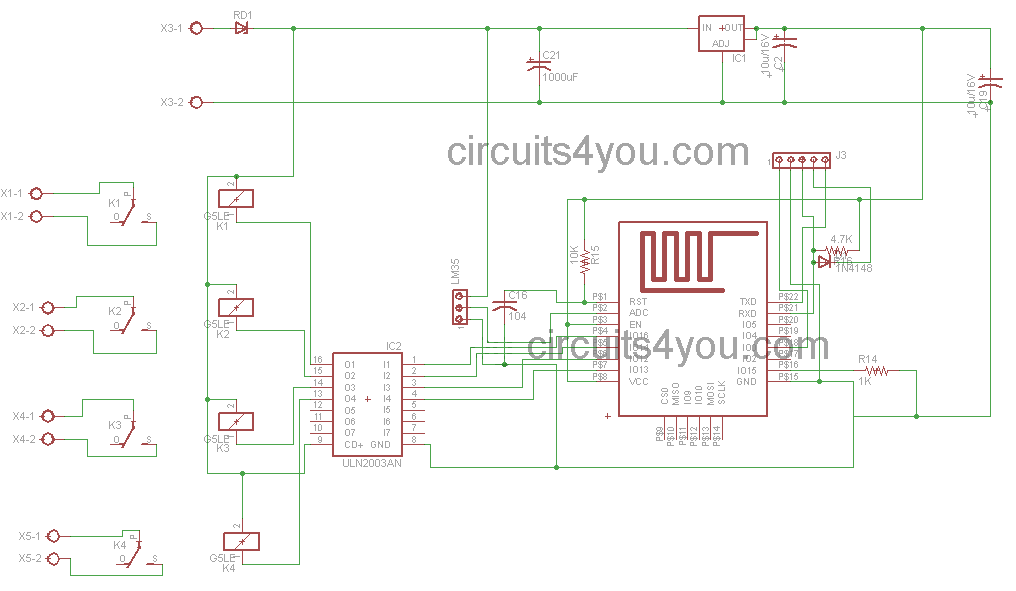
IoT Home Automation Circuit Diagram
From the circuit diagram it is very clear that we have used few components, LM1117-3.3V is used for providing power supply to the ESP-12 WiFi Module. ULN2003 provides relay driving.
PCB Layout of Home Automation
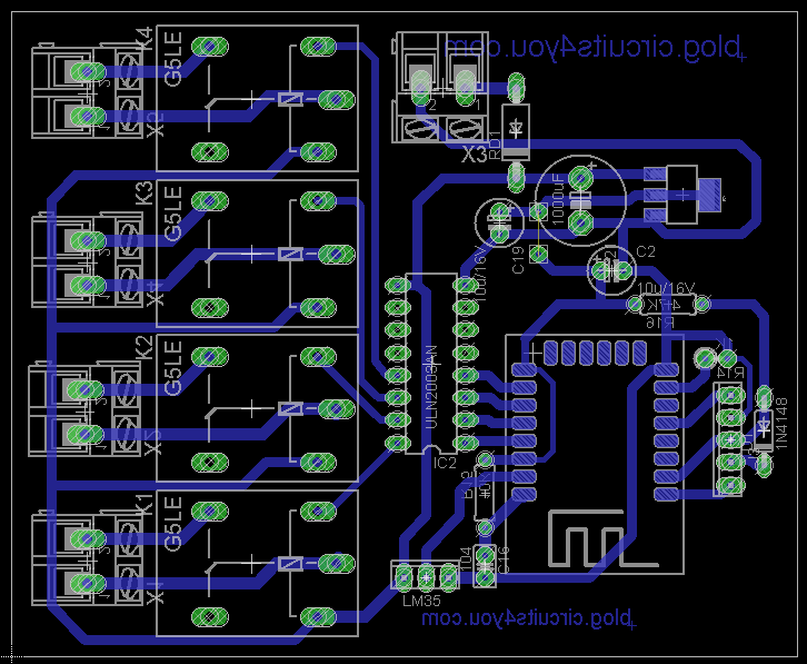
Download IOT Home Automation PCB Layout pdf
IoT Based Home Automation Code
main.ino
/*
 * Copyright (c) 2015, circuits4you.com
 * All rights reserved.
/* Create a WiFi access point and provide a web server on it. */
#include <ESP8266WiFi.h>
#include <WiFiClient.h>
#include <ESP8266WebServer.h>
#include "mainPage.h"
const int Load1=16;
const int Load2=14;
const int Load3=12;
const int Load4=13;
/* Set these to your desired credentials. */
const char *ssid = "HomeServer";
const char *password = "homeautomation";
ESP8266WebServer server(80);
String L1Status,L2Status,L3Status,L4Status,Temperature;
//=======================================================================
//                    handles main page 192.168.4.1
//=======================================================================
/* Just a little test message.  Go to http://192.168.4.1 in a web browser
 * connected to this access point to see it.
 */
void handleRoot() {
  String s = MAIN_page;
  s.replace("@@L1@@", L1Status);
  s.replace("@@L2@@", L2Status);
  s.replace("@@L3@@", L3Status);
  s.replace("@@L4@@", L4Status);
  s.replace("@@TEMP@@", Temperature);
  server.send(200, "text/html", s);
}
//=======================================================================
//                    Handle Set Date/Time Settings
//=======================================================================
void handleForm() {
  String t_state = server.arg("submit");

  Temperature = String(analogRead(A0)/10);   //Do calibration here

//Change Load-1 State as per request
  if(t_state=="ON1")
  {
    L1Status="ON";
    digitalWrite(Load1, HIGH);       //Load1 Turned on
  }

  if(t_state=="OFF1")
  {
    L1Status="OFF";
    digitalWrite(Load1, LOW);      //Load1 Turned off
  }
//Change Load-2 State as per request
  if(t_state=="ON2")
  {
    L2Status="ON";
    digitalWrite(Load2, HIGH);       //Load1 Turned on
  }

  if(t_state=="OFF2")
  {
    L2Status="OFF";
    digitalWrite(Load2, LOW);      //Load1 Turned off
  }
//Change Load-3 State as per request
  if(t_state=="ON3")
  {
    L3Status="ON";
    digitalWrite(Load3, HIGH);       //Load1 Turned on
  }

  if(t_state=="OFF3")
  {
    L3Status="OFF";
    digitalWrite(Load3, LOW);      //Load1 Turned off
  }
//Change Load-4 State as per request
  if(t_state=="ON4")
  {
    L4Status="ON";
    digitalWrite(Load4, HIGH);       //Load1 Turned on
  }

  if(t_state=="OFF4")
  {
    L4Status="OFF";
    digitalWrite(Load4, LOW);      //Load1 Turned off
  }
  server.sendHeader("Location", "/");
  server.send(302, "text/plain", "Updated-- Press Back Button");  //This Line Keeps It on Same Page

  delay(500);
}
//=======================================================================
//                    Power on setup
//=======================================================================
void setup() {
  delay(1000);
  /* You can remove the password parameter if you want the AP to be open. */
  WiFi.softAP(ssid, password);
  IPAddress myIP = WiFi.softAPIP();
  server.on("/", handleRoot);
  server.on("/form", handleForm);

  server.begin();
  pinMode(Load1, OUTPUT);
  pinMode(Load2, OUTPUT);
  pinMode(Load3, OUTPUT);
  pinMode(Load4, OUTPUT);
}
//=======================================================================
//                    Main Program Loop
//=======================================================================
void loop() {
  server.handleClient();
}
//=======================================================================
mainPage.h
const char MAIN_page[] PROGMEM = R"=====(
<HTML>
<TITLE>
REMOTE LED ON/OFF CONTROL
</TITLE>
<BODY>
<CENTER>
<FORM method="post" action="/form">
<TABLE>
<TR><TD colspan=2><B>IoT Based Home Automation System</B></TD></TR>
<TR><TD>Temp: @@TEMP@@ C</TD><TD>Load Status</TD></TR>
<TR><TD>
<INPUT TYPE=SUBMIT VALUE="ON1" name=submit>
<INPUT TYPE=SUBMIT VALUE="OFF1" name=submit>
</TD>
<TD>@@L1@@</TD></TR>
<TR><TD>
<INPUT TYPE=SUBMIT VALUE="ON2" name=submit>
<INPUT TYPE=SUBMIT VALUE="OFF2" name=submit>
</TD>
<TD>@@L2@@</TD></TR>
<TR><TD>
<INPUT TYPE=SUBMIT VALUE="ON3" name=submit>
<INPUT TYPE=SUBMIT VALUE="OFF3" name=submit>
</TD>
<TD>@@L3@@</TD></TR>
<TR><TD>
<INPUT TYPE=SUBMIT VALUE="ON4" name=submit>
<INPUT TYPE=SUBMIT VALUE="OFF4" name=submit>
</TD>
<TD>@@L4@@</TD></TR>
<TR><TD colspan=2><B><CENTER><A href = "https://circuits4you.com">www.circuits4you.com</a></CENTER></B></TD></TR>
</TABLE>
</FORM>
</CENTER>
</BODY>
</HTML>
)=====";
IoT based Home Automation Circuit Testing
1. Turn on the circuit
2. Turn on WiFi on your mobile or Laptop
3. Enter 192.168.4.1 Ip in browser
4. You will find this page and operate the relays
5. Connect Relay output to the electrical load

This is the simplest IOT Based Home Automation uses only ESP8266 Low cost iot module and relays.


Pls convert code into Ajax WebSockets.